Maglev Pen Stand
Probably the largest piece of aluminium I have purchased. Quite a lump!
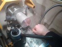
I drilled a hole through the side for the supporting arm, and as a cable entry point to the base. five cores run through the arm. the other two wires protuding are for the power supply. 7.5V 1A
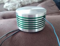
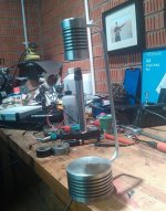
Here you can see the base is flipped over which reveals where the circuit board is hidden. inside here is three buttons for adjusting the power of the electromagnet to accommodate objects of different weight upto around 80 grams. at this stage bottles and things are propping it up as the supporting arm is not yet fixed in place. If you look closely, you can see there is two magnets levitating there with quite an impressive air gap.
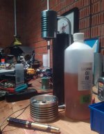
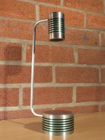
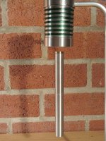
The top was machined from aluminium scaffolding, and the end pieces from solid bar. I wish I photographed the bottom end cap as that was quite intricate. the inside profile was made to cause the bottom cap to wrap around the height of the electromagnet to act as a heat sink. the endplug is also hollowed out so that the electromagnet is sitting on a 1mm layer of aluminium, just behind the black foam pad you can see in later pictures. This was done to maximise the air gap, as further into the enclosure the electromagnet goes, the further away from your pen it will be.
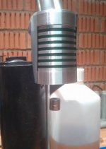
The make or break test. I sellotaped a couple of magnets onto the end of one of my pens to test it out, and was relieved that after a little bit of tweaking, the pen was levitating.
View attachment 21072
Techie stuff:
I programmed a PIC microprocessor to take a reading from a hall effect sensor which is placed in the end of the electromagnet. This sensor measures the electromagnetic field and adjusts the current of the electromagnet to compensate. Basically as the pen moves towards or away from the electromagnet the field changes, and the microprocessor compensates to either pull the pen closer, or let it move away, causing it to levitate.
Probably the largest piece of aluminium I have purchased. Quite a lump!

I drilled a hole through the side for the supporting arm, and as a cable entry point to the base. five cores run through the arm. the other two wires protuding are for the power supply. 7.5V 1A

Here you can see the base is flipped over which reveals where the circuit board is hidden. inside here is three buttons for adjusting the power of the electromagnet to accommodate objects of different weight upto around 80 grams. at this stage bottles and things are propping it up as the supporting arm is not yet fixed in place. If you look closely, you can see there is two magnets levitating there with quite an impressive air gap.

The top was machined from aluminium scaffolding, and the end pieces from solid bar. I wish I photographed the bottom end cap as that was quite intricate. the inside profile was made to cause the bottom cap to wrap around the height of the electromagnet to act as a heat sink. the endplug is also hollowed out so that the electromagnet is sitting on a 1mm layer of aluminium, just behind the black foam pad you can see in later pictures. This was done to maximise the air gap, as further into the enclosure the electromagnet goes, the further away from your pen it will be.

The make or break test. I sellotaped a couple of magnets onto the end of one of my pens to test it out, and was relieved that after a little bit of tweaking, the pen was levitating.

View attachment 21072


Techie stuff:
I programmed a PIC microprocessor to take a reading from a hall effect sensor which is placed in the end of the electromagnet. This sensor measures the electromagnetic field and adjusts the current of the electromagnet to compensate. Basically as the pen moves towards or away from the electromagnet the field changes, and the microprocessor compensates to either pull the pen closer, or let it move away, causing it to levitate.


